
Description
Features:
Simple connection:
A 3-core data link connects the alarm to the end of line transmitter, regardless of the number of gases.
Simple modular maintenance:
Control PCB 230vac via Wieland ST18 plug & socket.
Control and transmitter boards designed with pluggable data terminations and signal inputs.
The alarm components can be changed in less than 2 minutes, remove fascia via 2 fixing screws and PCB via 3 further screws and unplug.
Application:
Several SAX-6 alarms can be connected to the same end of line components using just 3 cores.
The SAX-6 can transmit a common alarm, using the MEDCON data protocol, for display on the SDX-15 plant alarm system
The SAX-6 can also receive data from the SDX-15 Plant Alarm system.
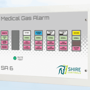
The SAX-6 area alarm is used to monitor pipeline pressure within a ward, theatre etc. The pressure is monitored by pressure switches in the pipeline downstream from the last AVSU. Pressure is monitored for both high and low pressure (low only for vacuum). The integrity of the cabling between the pressure switches and the alarm panel is monitored, and a fault on this cable will result in a system fault alarm, with all affected alarm conditions going into alarm condition.
The monitoring of the cable requires a termination box to be mounted as close as practical to the pressure switches. As an optional extra, these termination boxes can be supplied with the cables for connection to the pressure switches already fitted, allowing significant savings in on-site work.
To use more than one SAX-6 alarm panel with one set of pressure switches, simply connect all SAX-6 alarm panels to the 3 core screened cable (minimum 0.5mm) from the termination box (either at the termination box itself, or at another SAX-6).
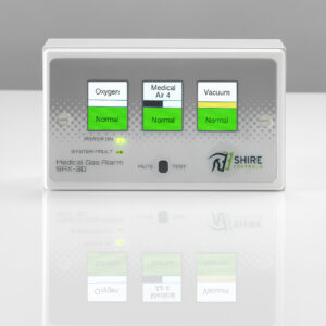
External Indicators:
SAX-6 has 3 LED indicators marked P, M & D on the front panel which indicate the following:
The P LED represents pressure switch inputs.
LED is off the panel has not been set up to detect pressure switch inputs via the end of line transmitter board.
LED is flashing, the SAX panel has been set up to receive pressure switch inputs, but has not been connected correctly to the end of line transmitter board.
LED is on, this indicates that the SAX panel and transmitter board are set up and communicating correctly.
The M LED represents use with our MEDCON protocol (as with our SDX Plant Alarm System).
LED is off the panel has not been set up to work with our SDX system and NO plug-in upgrade card has been installed.
LED is flashing, then a plug-in card has been installed to enable use with our SDX system, but the 2-core data bus used for such systems has not been connected correctly.
LED is on, this indicates that the SAX panel is working in conjunction with the SDX network and is capable of transmitting the local alarm conditions onto the SDX system.
The D LED is reserved for units with the main FPGA IC programmed to D type.
The LED is either on or off and is designed to show at a glance whether a unit incorporates the D type chip without having to open each unit up.
The purpose of the chip is to enable 2no panels (each 3 gas max) to provide status to 1no 6 gas central unit using standard boards and cabling.
Installation requirements:
A 230 vac supply, fused at 3 amps, fed from the essential supply
A 3 core screened cable (minimum 0.5mm) from the alarm panel to the termination board
All screens to be earthed at BOTH ends.
Termination Boxes
Equipment Warranty:
Warranty: alarms returned to our works which have failed due to faulty parts or manufacture will be repaired (or replaced) without charges for parts and labour.
10 year compatibility warranty: Install the SAX-6 with the confidence that equipment will be available to modify or extend the system for at least 10 years.
HTM0201 compliant (also BSEN 737 part 3 and BSEN 4754)
Product Part No
1 Gas SAX6 Alarm (Flush or Surface) c/w SATBTX in GW44206 sax1f or s
2 Gas SAX6 Alarm (Flush or Surface) c/w SATBTX in GW44206 sax2f or s
3 Gas SAX6 Alarm (Flush or Surface) c/w SATBTX in GW44206 sax3f or s
4 Gas SAX6 Alarm (Flush or Surface) c/w SATBTX in GW44206 sax4f or s
5 Gas SAX6 Alarm (Flush or Surface) c/w SATBTX in GW44206 sax5f or s
6 Gas SAX6 Alarm (Flush or Surface) c/w SATBTX in GW44206 sax6f or s
1 Gas SAX6 Pre-Wired c/w PCB saxpw1
2 Gas SAX6 Pre-Wired c/w PCB saxpw2
3 Gas SAX6 Pre-Wired c/w PCB saxpw3
4 Gas SAX6 Pre-Wired c/w PCB saxpw4
5 Gas SAX6 Pre-Wired c/w PCB saxpw5
6 Gas SAX6 Pre-Wired c/w PCB saxpw6
SAX/SDX Adaptor PCB saxsdx
SAX Computer Interface in GW44208 saxci
Surface Back Box saxboxsurfacebase
Surface Fascia saxboxtops
Flush Back Box (shal/deep) saxboxf or saxboxfd
Flush Bezel saxflushfascia
Battery 12 volt Sh435
Battery 12 volt 20+ (No Test) sh435
Membrane & Window sh766
Weather Proof Box sh700
1 Gas Control PCB sax1control
2 Gas Control PCB sax2control
3 Gas Control PCB sax3control
4 Gas Control PCB sax4control
5 Gas Control PCB sax5control
6 Gas Control PCB sax6control
SAX Transmitter PCB In Box satbtx6
SAX Transmitter PCB Only satbtx6board
SAX/SDX Adaptor PCB saxsdx
SAX Transmitter BOX Only (44206) sh474
SAX6 Computer Interface PCB Only saxcipretest
1 Gas Upgrade saxadd x 1
2 Gas Upgrade saxadd x 2
3 Gas Upgrade saxadd x 3
4 Gas Upgrade saxadd x 4
5 Gas Upgrade saxadd x 5
Retest saxtest
Rechip saxchip
Low Pressure c/w O Ring & Boot psw1
High Pressure c/w O Ring & Boot pswh
Vacuum Switch c/w O Ring & Boot pswv
Twin Manifold with 15mm stub c/w High & Low Pressure Switches, O Rings & Boots pssass2
Single Manifold with 15mm stub c/w Vacuum Switch (or Low Pressure Switch), O Ring & Boot pssass1
Twin Manifold with 15mm stub sh701
Single Manifold with 15mm stub sh340