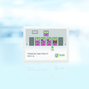
SA6 Area Alarm
Class 1 Medical Device: Medical Gas Pipeline Systems
For more information & documentation please Contact us.
Features:
Connection:
The simple, robust design allows analogue inputs to be connected via end of line termination units (or directly). A multi-core connection is made from the end of line transmitter (or contact source) to the alarm, comprising a single ‘common’ plus one core per condition to be monitored. Since its introduction over 30 years ago, the SA6 Area Alarm has been re-issued on a number of occasions, but newer versions have always been designed to ensure that current issue PCBs are compatible with previous designs. The SA6 has sold over 30,000 units around the world, is known for its reliability and has been called the ‘industry standard’, which is why we continue to manufacture and support this product with no plans to de-list.
Application:
The SA-6 area alarm is used to monitor pipeline pressure within a ward, theatre etc. The pressure is monitored by pressure switches in the pipeline downstream from the last AVSU. Pressure is monitored for both high and low pressure (low only for vacuum). The integrity of the cabling between the pressure switches and the alarm panel is monitored, and a fault on this cable will result in the following:-
A system fault alarm
The alarm condition(s) affected by the fault going into alarm condition.
The monitoring of the cable requires a termination board to be mounted as close as practical to the pressure switches. The termination boards are supplied as bare PCBs which must be mounted in an enclosure. As optional extras, these termination boards can be supplied already mounted in a box, or mounted in a box together with the cables for connection to the pressure switches already fitted, allowing significant savings in on-site work. When an SA-6 alarm is mounted in a zone module or AVSU, where the pressure switches are in the same enclosure as the alarm panel, cable monitoring is not required and therefore termination boards are not required. The alarm panel can be set to operated with or without termination boards (please specify when ordering).
The SA-6 alarm panels can be used in a master-slave configuration, with a maximum of 2 slaves from a master, using a three core screened cable (minimum 0.5mm) to connect the alarm panels, with a maximum of 100 metres of cable on the system. Note that if 2 slaves are used, the three core cable must run from master to first slave and then first slave to second slave NOT from master to first slave and master to second slave.
Installation requirements:
A 230 vac supply, fused at 3 amps, fed from the essential supply
A screened cable (minimum 0.5mm) from the alarm panel to the termination board (1 core per alarm condition + common)
All screens to be earthed at BOTH ends.
Termination Boxes (optional)
Equipment Warranty:
Warranty: alarms returned to our works which have failed due to faulty parts or manufacture will be repaired (or replaced) without charges for parts and labour.
10 year compatibility warranty: Install the SA-6 with the confidence that equipment will be available to modify or extend the system for at least 10 years.
HTM 02-01 Compliant.
| Product | Part No |
| 3 Gas SA6 Alarm (Flush or Surface) | sa3f or s |
| 6 Gas SA6 Alarm (Flush or Surface) | sa6f or s |
| 1 Gas SA6 Pre-Wired in GW Box | pwbox1g |
| 2 Gas SA6 Pre-Wired in GW Box | pwbox2g |
| 3 Gas SA6 Pre-Wired in GW Box | pwbox3g |
| 4 Gas SA6 Pre-Wired in GW Box | pwbox4g |
| 5 Gas SA6 Pre-Wired in GW Box | pwbox5g |
| 6 Gas SA6 Pre-Wired in GW Box | pwbox6g |
| SA6 Computer Interface in GW44209 | saci |
| Surface box | saboxsas |
| Flush box | saboxsaf |
| Flush Bezel | safbez |
| Front Plate+Membrane | saplasy |
| Battery 6 volt | sh002 |
| Battery 12 volt | sh404 |
| Blanking plate | sh962 |
| Weather Proof Box | sh700 |
| 3 Gas Control Board | sa3control |
| 6 Gas Control Board | sa6control |
| 6 Gas Power Supply | saps |
| TB4 Termination PCB | TB4 |
| SA6 Computer Interface PCB | sacipcb |
| 1 Gas Upgrade | saadd x 1 |
| 2 Gas Upgrade | saadd x 2 |
| 3 Gas Upgrade | saadd x 3 |
| 4 Gas Upgrade | saadd x 4 |
| 5 Gas Upgrade | saadd x 5 |
| Retest | satest |
| Rechip | sachip |
| Low Pressure c/w O Ring & Boot | psw1 |
| High Pressure c/w O Ring & Boot | pswh |
| Vacuum Switch c/w O Ring & Boot | pswv |
| Twin Manifold with 15mm stub c/w High & Low Pressure Switches, O Rings & Boots | pssass2 |
| Single Manifold with 15mm stub c/w Vacuum Switch (or Low Pressure Switch), O Ring & Boot | pssass1 |
| Twin Manifold with 15mm stub | sh701 |
| Single Manifold with 15mm stub | sh340 |


